208 Results
View results:
Sort by:

This article describes and explains the influence of bending stiffness of cables on their internal forces. Furthermore, the text provides information on how this influence can be reduced.

Lateral-Torsional Buckling (LTB) is a phenomenon that occurs when a beam or structural member is subjected to bending and the compression flange is not sufficiently supported laterally. This leads to a combination of lateral displacement and twisting. It is a critical consideration in the design of structural elements, especially in slender beams and girders.

Wind direction plays a crucial role in shaping the outcomes of Computational Fluid Dynamics (CFD) simulations and the structural design of buildings and infrastructures. It is a determining factor in assessing how wind forces interact with structures, influencing the distribution of wind pressures, and consequently, the structural responses. Understanding the impact of wind direction is essential for developing designs that can withstand varying wind forces, ensuring the safety and durability of structures. Simplified, the wind direction helps in fine-tuning CFD simulations and guiding structural design principles for optimal performance and resilience against wind-induced effects.

When it comes to wind loads on building type structures as per ASCE 7, numerous resources can be found to supplement design standards and aid engineers with this lateral load application. However, engineers may find it more difficult to find similar resources for wind loading on non-building type structures. This article will examine the steps to calculate and apply wind loads as per ASCE 7-22 on a circular reinforced concrete tank with a dome roof.

This example shows you how to quickly determine the buoyancy or the uplift limit state of a vessel in RFEM.

Both the determination of natural vibrations and the response spectrum analysis are always performed on a linear system. If nonlinearities exist in the system, they are linearized and thus not taken into account. They are caused by, for example, tension members, nonlinear supports, or nonlinear hinges. This article shows how you can handle them in a dynamic analysis.

If you want to use a pure surface model, for example, when determining the internal forces and moments, but the structural component is still designed on the member model, you can take advantage of a result beam.

When a concrete slab is set upon the top flange, its effect is like a lateral support (composite construction), preventing problems of torsional buckling stability. If there is a negative distribution of the bending moment, the bottom flange is subjected to compression and the top flange is under tension. If the lateral support given by the stiffness of the web is insufficient, the angle between the bottom flange and the web intersection line is variable in this case so that there is a possibility of distortional buckling for the bottom flange.

For the stability verification of members using the equivalent member method, it is necessary to define effective or lateral-torsional buckling lengths in order to determine a critical load for stability failure. In this article an RFEM 6-specific function is presented, by which you can assign an eccentricity to the nodal supports and thus influence the determination of the critical bending moment considered in the stability analysis.

In RFEM 6, the results for the FE mesh nodes are determined using the finite element method. For the distribution of internal forces, deformations, and stresses to be continuous, these nodal values are smoothed through an interpolation process. This article will introduce and compare the different types of smoothing that you can use for this purpose.

As you may already know, RFEM 6 offers you the possibility to consider material nonlinearities. This article explains how to determine internal forces in slabs modeled with nonlinear material.

Line releases are special objects in RFEM 6 that allow structural decoupling of objects connected to a line. They are mostly used to decouple two surfaces that are not rigidly connected or transferring only compressive forces at the common boundary line. By defining a line release, a new line is generated at the same place which transfers only the locked degrees of freedom. This article will show the definition of line releases in a practical example.

This article shows you how to create contacts between two or more parallel surfaces by controlling the transfer of forces between them.

A standard scenario in timber member construction is the ability to connect smaller members by means of bearing on a larger girder member. Additionally, member end conditions may include a similar situation where the beam is bearing on a support type. In either scenario, the beam must be designed to consider the bearing capacity perpendicular to the grain according to NDS 2018 Sec. 3.10.2 and CSA O86:19 Clauses 6.5.6 and 7.5.9. In general structural design software, it is typically not possible to carry out this full design check, as the bearing area is unknown. However, in the new generation RFEM 6 and Timber Design add-on, the added 'design supports' feature now allows users to comply with the NDS and CSA bearing perpendicular to the grain design checks.

The optimal scenario in which punching shear design according to ACI 318-19 [1] or CSA A23.3:19 [2] should be utilized is when a slab is experiencing a high concentration of loading or reaction forces occurring at one single node. In RFEM 6, the node in which punching shear is an issue is referred to as a punching shear node. The causes of these high concentration of forces can be introduced by a column, concentrated force, or nodal support. Connecting walls can also cause these concentrated loads at wall ends, corners, and ends of line loads and supports.

This article shows you the internal forces and displacements of a continuous beam calculated both with and without consideration of shear stiffness.

The stand-alone program RSECTION is at your disposal for determining section properties and performing stress analysis for thin-walled and massive cross-sections. The program can be connected to both RFEM and RSTAB so that sections from RSECTION are also available in the RFEM and RSTAB library. Likewise, internal forces from RFEM and RSTAB can be imported into RSECTION.

RSECTION 1 is a stand-alone program for determining section properties for both thin-walled and massive cross-sections, as well as for performing a stress analysis. In addition, the program can be connected to both RFEM and RSTAB: sections from RSECTION are available in the RFEM/RSTAB libraries, and internal forces from RFEM/RSTAB can be imported into RSECTION.

In RFEM 6, seismic analysis can be done by using the Modal Analysis and the Response Spectrum Analysis add-ons. Once the spectral analysis has been performed, it is possible to use the Building Model add-on to display story actions, interstory drifts, and forces in shear walls.

To perform deflection analysis in the right manner, it is important to “inform” the program about the exact support conditions of the element of interest. The definition of design supports in RFEM 6 will be shown for a reinforced concrete member set.

Imperfections in construction engineering are associated with production-related deviation of structural components from their ideal shape. They are often used in a calculation to determine the equilibrium of forces for structural components on a deformed system.

The punching shear design, in line with EN 1992-1-1, should be performed for slabs with a concentrated load or reaction. The node where the design of punching shear resistance is performed (that is, where there is a punching problem) is called a node of punching shear. The concentrated load at these nodes can be introduced by columns, concentrated force, or nodal supports. The end of the linear load introduction on slabs is also regarded as a concentrated load and therefore, the shear resistance at wall ends, wall corners, and ends or corners of line loads and line supports should be controlled as well.

The stability checks for the equivalent member design according to EN 1993-1-1, AISC 360, CSA S16, and other international standards require consideration of the design length (that is, the effective length of the members). In RFEM 6, it is possible to determine the effective length manually by assigning nodal supports and effective length factors or, on the other hand, by importing it from the stability analysis. Both options will be demonstrated in this article by determining the effective length of the framed column in Image 1.

Complex structures are assemblies of structural elements with various properties. However, certain elements can have the same properties in terms of supports, nonlinearities, end modifications, hinges, and so on, as well as design (for example, effective lengths, design supports, reinforcement, service classes, section reductions, and so on). In RFEM 6, these elements can be grouped on the basis of their shared properties and thus can be considered together for both modeling and design.

This article describes how a flat slab of a residential building is modeled in RFEM 6 and designed according to Eurocode 2. The plate is 24 cm thick and is supported by 45/45/300 cm columns at distances of 6.75 m in both the X and Y directions (Image 1). The columns are modeled as elastic nodal supports by determining the spring stiffness based on the boundary conditions (Image 2). C35/45 concrete and B 500 S (A) reinforcing steel are selected as the materials for the design.

RFEM 6 includes the Form-Finding add-on to determine the equilibrium shapes of surface models subjected to tension and members subjected to axial forces. Activate this add-on in the model's Base Data and use it to find the geometric position in which the prestress of lightweight structures is in equilibrium with the existing boundary conditions.

This technical article presents some basics for using the Torsional Warping add-on (7 DOF). It is fully integrated into the main program and allows you to consider the cross-section warping when calculating member elements. In combination with the Stability Analysis and Steel Design add-ons, it is possible to perform the lateral-torsional buckling design with internal forces according to the second-order analysis, taking imperfections into account.

In order to create a surface model with failing supports close to reality, an option called "Failure if contact perpendicular to surfaces failed" is available in RFEM 5 for contact solids under "Contact Parallel to Surfaces".
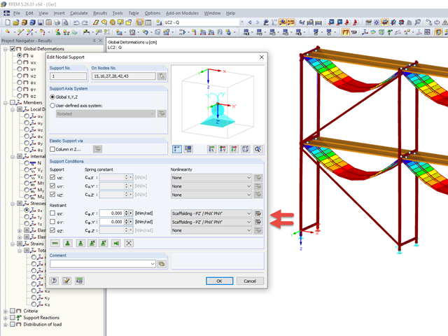
Temporary structures, such as scaffolding or props, are versatile structures that can be adapted very well to different geometric conditions.

For line supports, there is an option to graphically display the additional information for all directions.